Surface-Stable Fractal Dither on Playdate
Rune Skovbo Johansen has a really sweet Surface-Stable Fractal Dithering technique, where the dither dots “stick” to 3D surfaces, yet the dot density adapts to the view distance and zoom level.
Some people have asked whether this would be a good technique for Playdate, given that the screen
is one-bit color. And so I had to try it out! Here’s a video:
And here’s the code: github.com/aras-p/playdate-dither3d.
This is a long-arse post, so here’s the sections:
Is it practical?
My impression: not really practical.
Playdate hardware is like a PC from 1995 - no GPU at all, one fairly simple CPU core. As such, it can do fairly simple 3D rendering (well, you need to write the whole rasterizer on the CPU), but can barely do more than a handful of math operations per rasterized pixel. Rasterizing with screen-space fixed Bayer or Blue Noise dither patterns is the way to go due to their simplicity.
You can barely do textured triangles, whereas cost of Fractal Dithering is, with some simplifications, at least twice that (you still need to interpolate the texture coordinates, do some additional math on them, do a 3D texture lookup, and additional math on that).
But, while doing this, I’ve learned a thing or two about software rasterizers. Of course, everyone else has learned that in 1997, but I’ve never written a perspective-correct textured triangle rasterizer… As the old saying goes, “the best time to write a triangle rasterizer was thirty years ago. The second best time is today.” So what follows is various notes I have made during the process.
Surface-Stable Fractal Dithering
Rune has a really great video explaining the technique, and an extended feature demo video, plus all the source in the github repository, with most of the shader logic being in Dither3DInclude.cginc HLSL shader file.
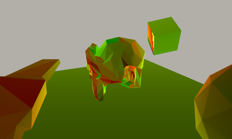
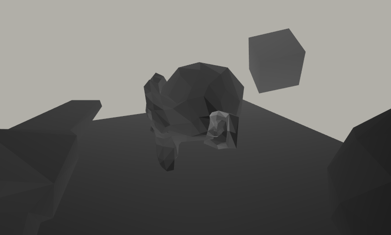
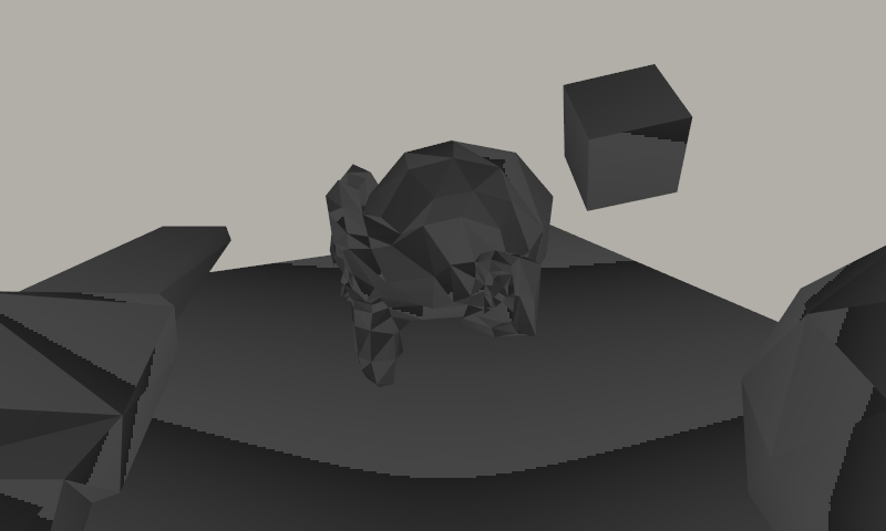
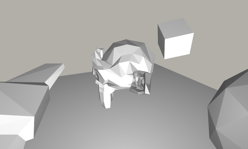
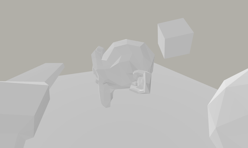
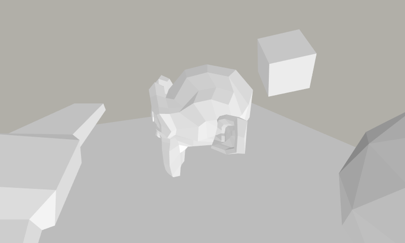
Here’s an outline of the steps. We have some scene where the input for dithering is “brightness”:
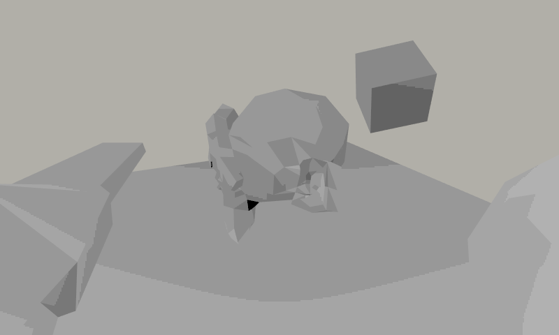
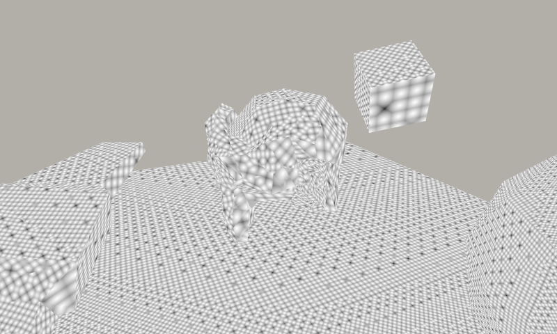
And the Surface-Stable Fractal Dithering (with a 4x4 dither pattern) turns it into this:
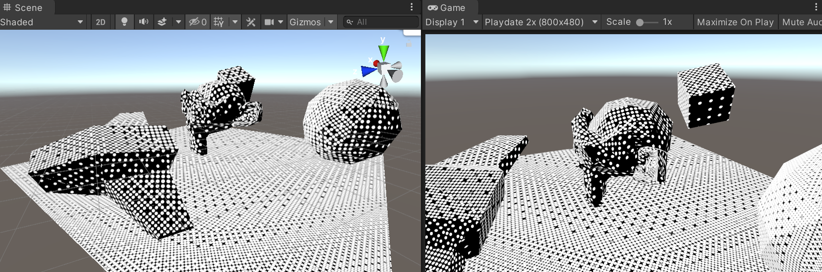
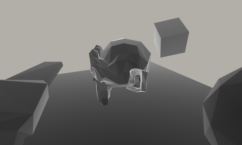
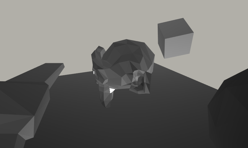
Now, the dots above are still nicely anti-aliased; whereas Playdate is strictly 1-bit screen. Giving it only
two colors, and making them similar to how the device screen looks like, the result would be like this (note that
resolution here is 2x larger than Playdate, i.e. 800x480):
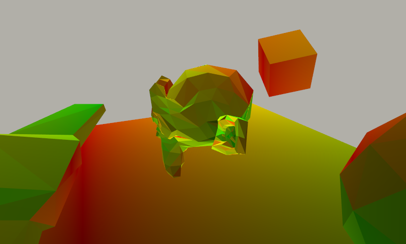
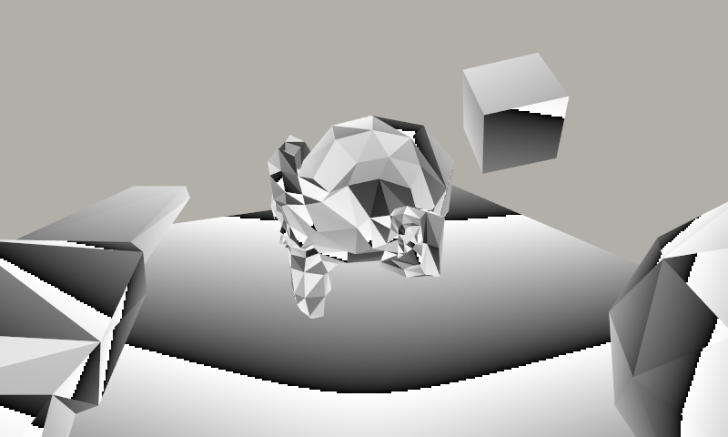
In addition to brightness, the dithering process needs geometry texture coordinates (“UVs”) as well. The dithering
pattern “sticks” to the surfaces by placing them in UV space.
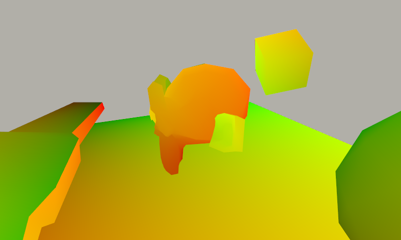
It also needs the derivatives of UVs in screen space, to know “how fast” they change across the screen projection. That
will be used to make sure the dither pattern is roughly constant size on screen. On the GPU, the derivatives
fall out naturally out of 2x2 pixel execution pattern, and in HLSL are provided by ddx and ddy built-in functions.
Here they are, visualized as abs(ddx(uv))*100 and abs(ddy(uv))*100 respectively:
Now, given these four derivative values, the technique uses singular value decomposition to find the minimum and
maximum rate of change (these might not be aligned to screen axes). The maximum and minimum frequencies (scaled up 30x)
look like:
The minimum frequency, together with user/material-specified dot spacing factor, gets turned into base
dither dot spacing value:
Then it is further adjusted by input brightness (if “size variability” material parameter is zero), so that
the actual dots stay roughly the same size, but in darker areas their spacing spreads further out.
This spacing is then used to calculate two factors used to sample a 3D lookup texture: 1) by which power
of two to adjust the mesh UVs so that the dither dots pattern is placed onto surface properly, and 2) which
actual dither pattern “slice” to use, so that the pattern more or less seamlessly blends between powers-of-two
levels.
The mesh UVs, adjusted for 3D texture sampling, look like this, as well as indication which Z slice of the texture to use:
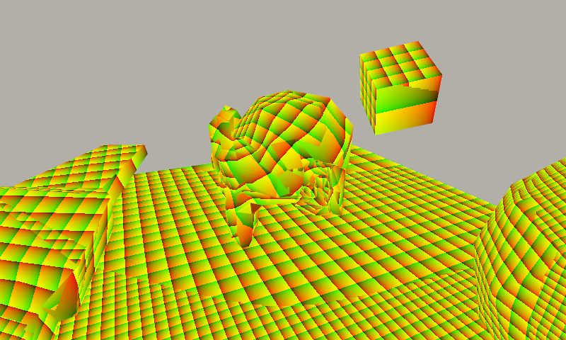
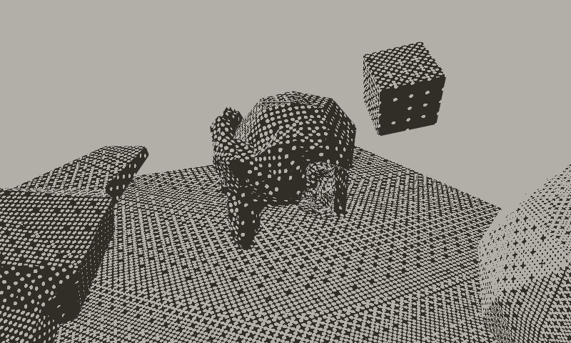
Result of sampling the 3D lookup texture (that was prepared ahead of time) is:
The 3D texture itself for the 4x4 dither pattern (64x64x16, with 3D texture slices side by side) looks like this:

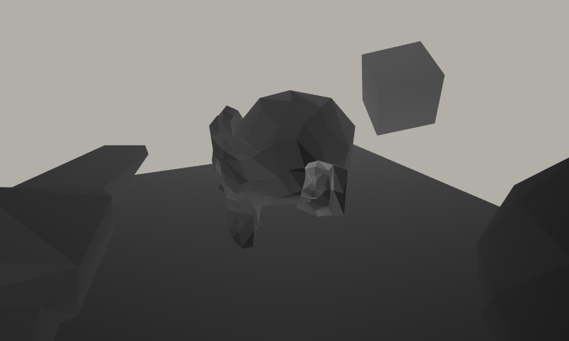
We’re almost there! Next up, the algorithm calculates contrast factor, which is based on material settings,
dot spacing, and the ratio of minimum and maximum UV rate of change. From that, the base brightness value
that the contrast is scaled around is calculated (normally it would be 0.5, but where the pattern would be very blurry
that would look bad, so there it is scaled away). And finally, the threshold value to compare the radial gradient from
3D texture is calculated based on input brightness. The contrast, base value and threshold respectively look like:
And finally we get our result:
So all of that was… <takes a quick look> something like one 3D texture sample, 4 divisions, 2 raises to a power, 3 square roots, 3 exp2s, 1 log2, and several dozen regular multiplies or additions for every pixel. Provided you have UVs and their derivatives already, that is.
That should, like, totally fly on a Playdate, right? 🥹
Anyway, let’s do this! But first…
Perspective correct texturing
Triangles have texture coordinates defined at their vertices, and while rasterizing the triangle, you interpolate
the texture coordinates, and at each pixel, read the texture value corresponding to the interpolated coordinate.
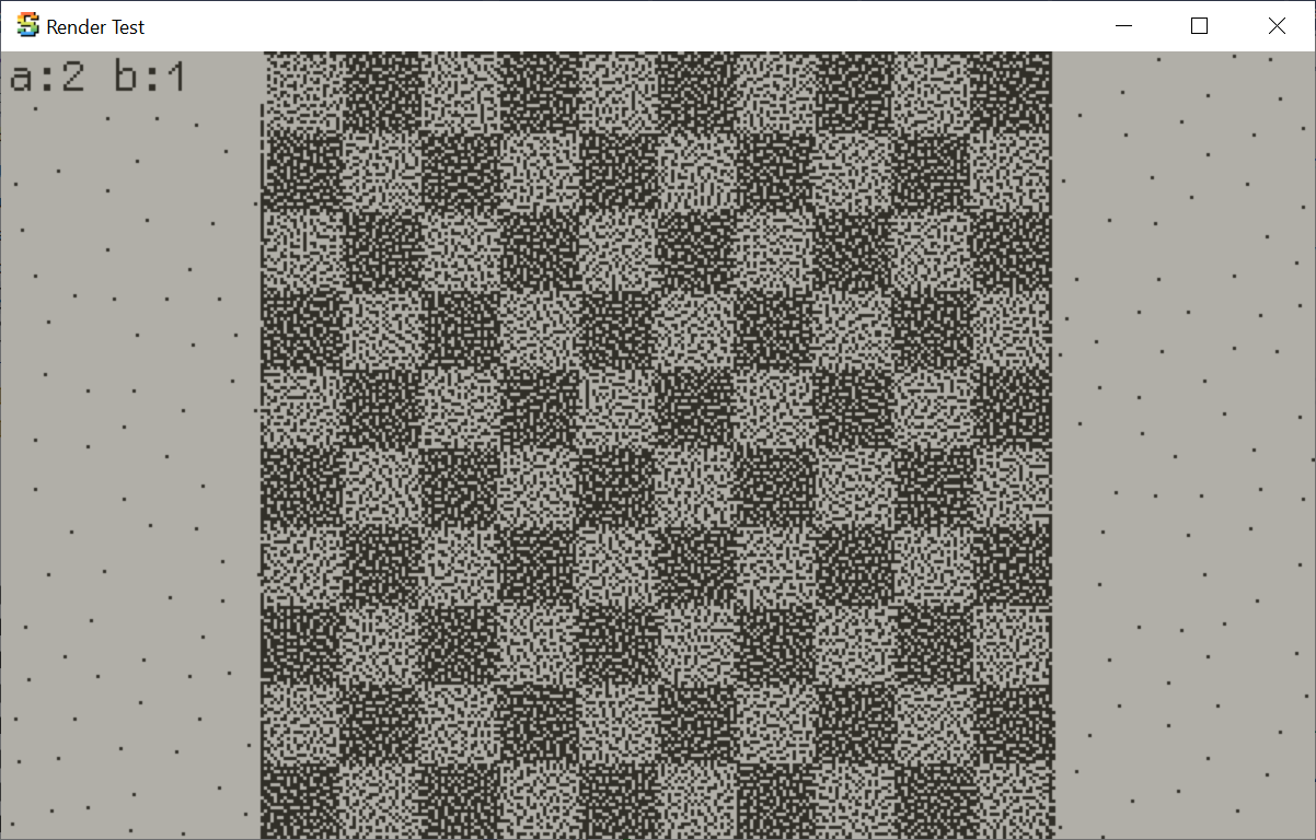
Here’s a simple checkerboard texture using interpolated UVs (ignore the noisy dithering; it is unrelated):
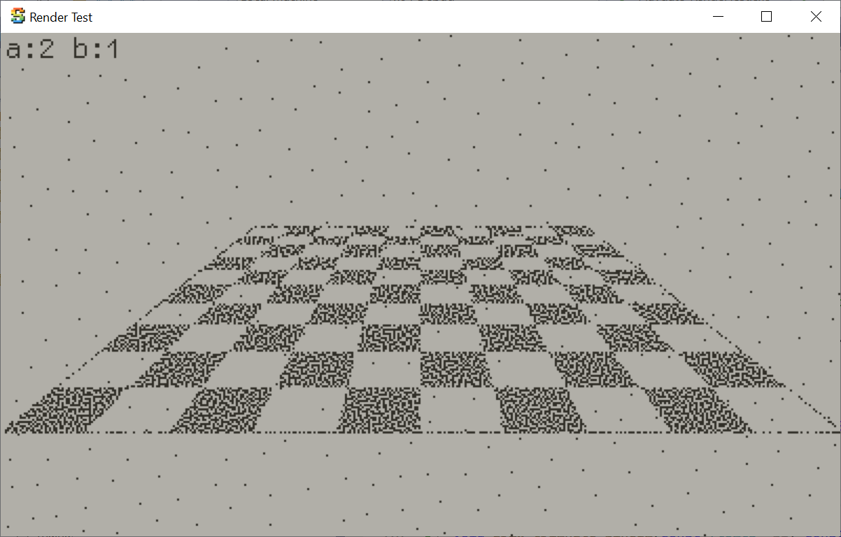
However, if we look at the same mesh at an angle, it looks really weird:

That is because under perspective projection, you need to use
perspective correct texture mapping,
and not just simply interpolate UVs in screen space. With perspective correction things look good, however that
means now we have to do a division per-pixel. And, divisions are slow. Anyway, this is the least of our problems
(for now…).
Displaying brightness on a Playdate
Playdate hardware has 1-bit “memory LCD” display: each pixel
can only be “on” or “off”. So typically to display “brightness”, some sort of dithering is used. The example
simple 3D rasterizer included in the Playdate SDK (“mini3d”) contains code
that rasterizes triangles using different patterns based on brightness:
Another common approach is to use a blue noise texture
for thresholding the brightness. I’ve used that approach in “Everybody Wants to Crank the World”
Playdate demo as well.

So the question now is, could Surface-Stable Fractal Noise be another approach to display “brightness” on a 1-bit Playdate screen?
“Porting” Surface-Stable Fractal Noise to Playdate
I had a triangle rasterizer based on Fabian Giesen’s “Simple watertight triangle rasterizer” working on a Playdate. This is a half-space / barycentric rasterizer, which is a good fit for hardware or modern CPUs with SIMD instruction sets. It might be a bad fit for Playdate CPU, but for now we’re not very concerned with that. The code is nice and small; further recommended reading from Fabian are “The barycentric conspiracy”, “Triangle rasterization in practice”, “Optimizing the basic rasterizer” blog posts, as well as “Fast software rasteriser in JavaScript?” discussion on pouët.
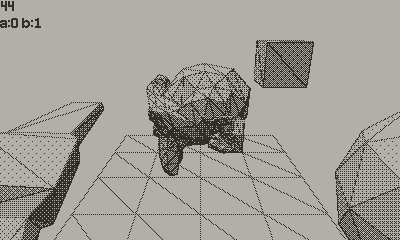
Initial port of Rune’s dithering shader code on a Playdate looked like this:
Welp, this does not look correct at all. Time to debug where exactly it goes wrong!
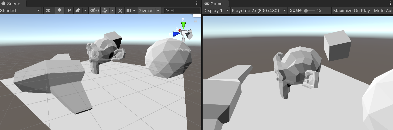
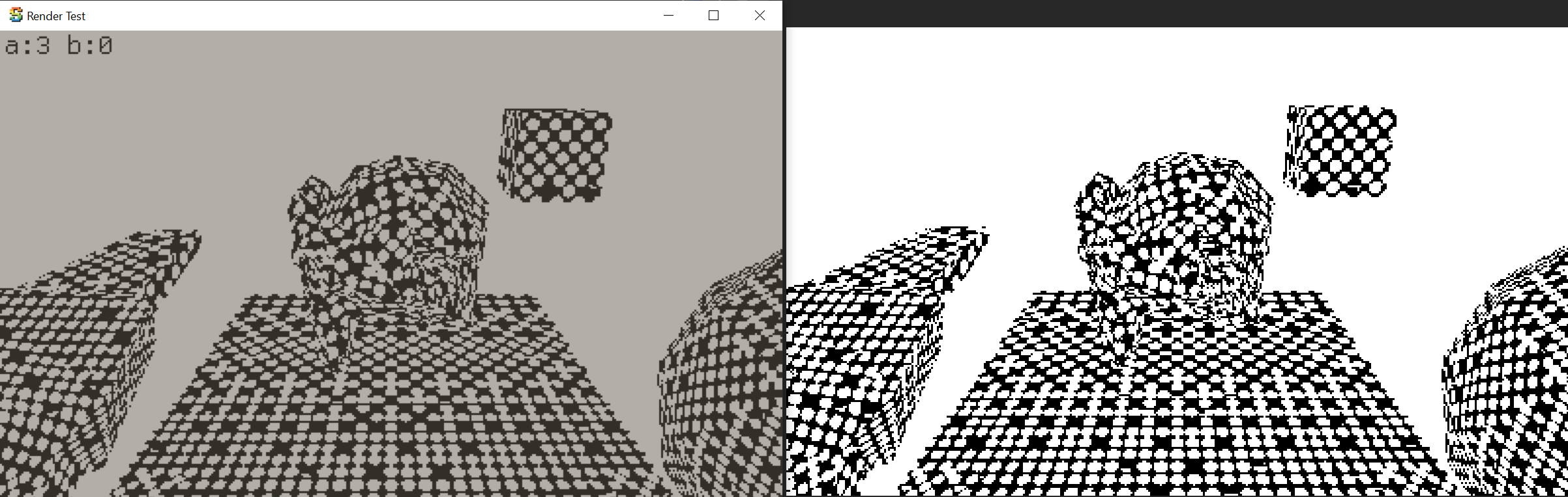
For development convenience, I have the whole “playdate application” setup as both a Playdate build target, and an application that can build for PC. There’s a super tiny “platform abstraction” that provides pointer to “screen”, as well as input controls handling, and on a Playdate that goes directly into the SDK, whereas on a PC that is all handled through Sokol. Is nice!
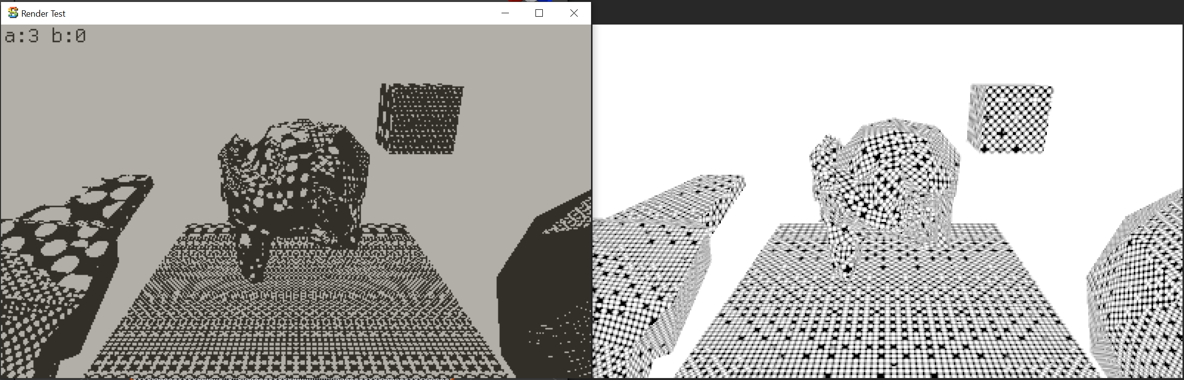
For the “PC” build target, in addition to the regular 1-bit “screen” buffer, I also have a full-color
“RGBA per pixel” debug overlay buffer. That way I can have the correct shader with some debug visualizations
running in Unity, and my own “shader port” running in a software rasterizer, side by side, with
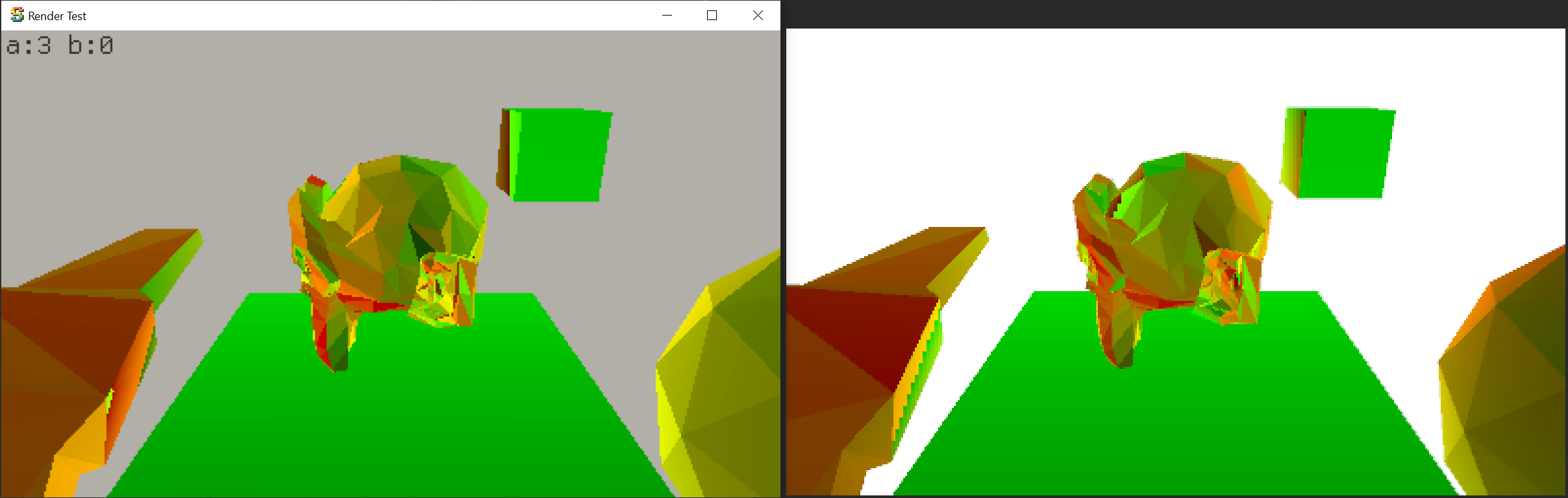
a full color debug overlay. Check it out – left side my code (displaying obviously incorrect result),
right side Unity:
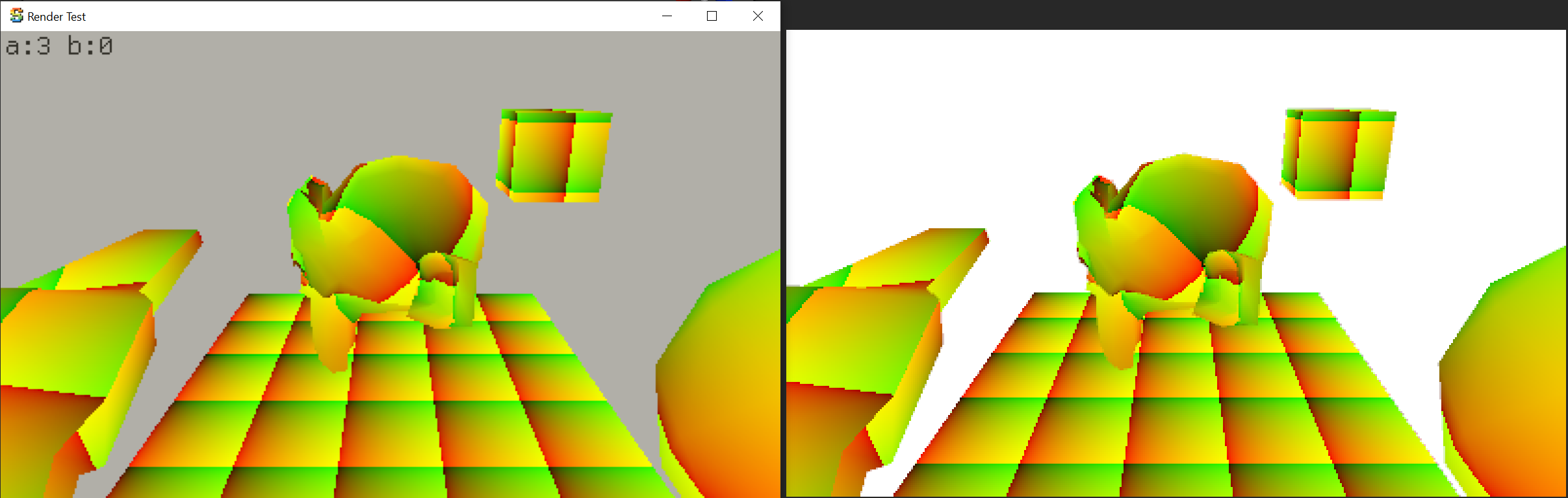
The mesh UVs are correct and interpolated correctly (multiplied by 5 to see their interpolation better):
Derivatives in my code, turns out, were not entirely wrong, but not correct either:
At that point my rasterizer was doing 1 pixel at a time, so in order to calculate the derivatives
I tried to calculate them with some math, and got the math wrong, obviously. With the full
proper calculation, they were correct:
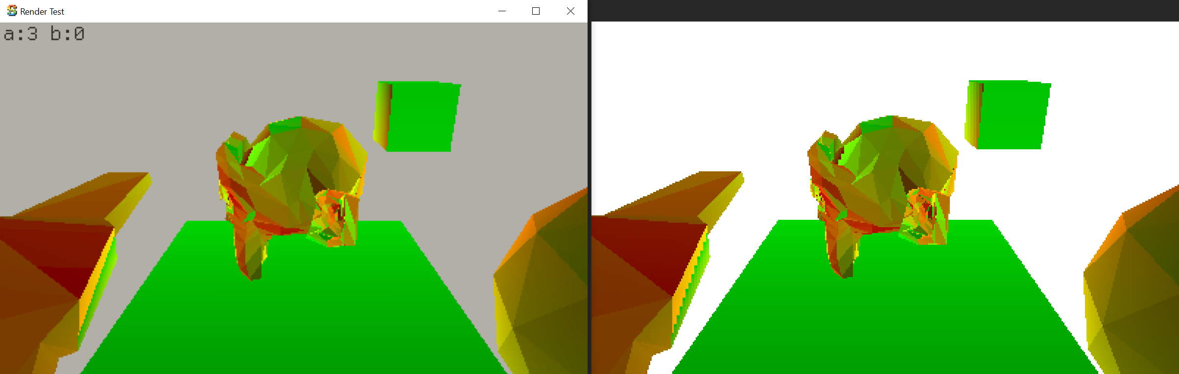
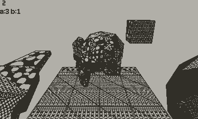
Turns out I also had the 3D texture Z layers order wrong, and with that fixed, everything else
was correct too. Dither UVs, 3D texture radial pattern, render result, render result with 2 colors
only, and finally render result with non-constant input lighting:


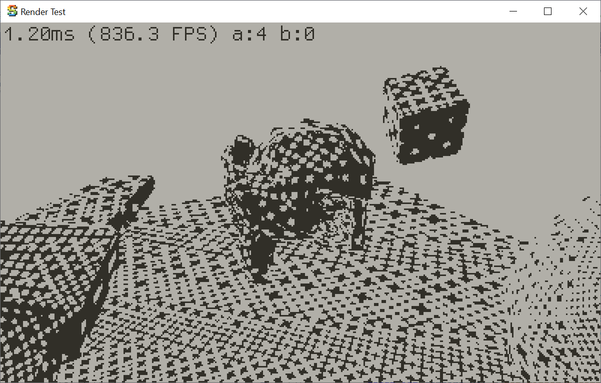
So, yay! It works!
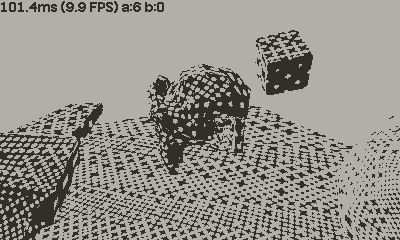
It runs at… 830 milliseconds per frame though (1.2FPS). 🐌
Optimizing Fractal Dithering
Trivially move some math from per-pixel to be done once per triangle: 604ms.
Replace division and exp2f call by directly working on floating point bits. If we are in “regular floats”
range (no NaNs/infinities/denormals), x / exp2f((float)i) can be replaced by something like:
// equivalent to `x / exp2f((float)i)`, provided we are not in
// infinities / subnormals territory.
static inline float adjust_float_exp(float x, int i)
{
    union {
        float f;
        uint32_t u;
    } fu;
    fu.f = x;
    fu.u -= (uint32_t)i << 23;
    return fu.f;
}
In the dither shader, this was used to transform mesh UVs to the fractal pattern UVs. That gets us down to 316ms, yay! (by the way, such an optimization for today’s GPUs is barely – if at all – worth doing)
Likewise, in the 3D texture fractal level and fraction calculation that uses log2f and a floorf
can also be replaced with direct float bit manipulation:
//float spacingLog = log2f(spacing);
//const float patternScaleLevel = floorf(spacingLog); // Fractal level.
//const int patternScaleLevel_i = (int)patternScaleLevel;
//float f = spacingLog - patternScaleLevel; // Fractional part.
//
// instead of above, work on float bits directly:
union {
    float f;
    uint32_t u;
} fu;
fu.f = spacing;
// patternScaleLevel is just float exponent:
const int patternScaleLevel_i = (int)((fu.u >> 23) & 0xFF) - 127;
// fractional part is:
// - take the mantissa bits of spacing,
// - set exponent to 127, i.e. range [0,1)
// - use that as a float and subtract 1.0
fu.u = (fu.u & 0x7FFFFF) | 0x3F800000;
float f = fu.f - 1.0f;
And now we are at 245ms.
And now, switch the rasterizer to operate in 2x2 pixel blocks (hey, just like a GPU does!). This does make the code much longer (commit), but things like derivatives come “for free”, plus it allows doing a bunch of calculations (all the dither dot spacing, 3D texture level etc.) once per 2x2 pixel block. 149ms.
Some more simple math operation moves and we’re at 123ms.
At this point I was out of easy ideas, so I decided that running “full” effect on a Playdate is not going to work, so it is time to simplify / approximate it.
The effect spends quite some effort in determining nice “contrast” value, but it comes with a cost:
doing singular value decomposition on the four derivatives, a division, and a bunch of other maths.
Let’s remove all that, and instead determine dither pattern spacing by a simple average of dU/dX,
dV/dX, dU/dY, dV/dY. Then there’s no longer additional contrast tweak based on “blurriness”
(ratio of min/max UV change). However, it runs at 107ms now, but looks different:


The 3D lookup texture for dithering, at 64x64x16 resolution, is 64 kilobytes in size. The CPU
cache is only 8KB, and the memory bandwidth is not great. Maybe we could reduce the texture horizontal
resolution (to 32x32x16), for a 16KB texture, and it would not reduce quality all that much? Looks
a bit different, but hey, 83ms now:

Instead of doing perspective correct UV interpolation for every pixel, do it for every
2nd pixel only, i.e. for the first column of each 2x2 pixel block. For the other column,
do regular interpolation between this and next block’s UV values
(commit). 75ms:

Simplify the final math that does sampled 3D texture result comparison, now it is just a simple
“compare value with threshold”. 65ms:

At this point I was out of easy ideas how to speed it up further (harder ideas: do perspective correct interpolation at even lower frequency). However, anecdotally, the whole current approach of using halfspace/barycentric rasterizer is probably not a good fit for the Playdate CPU (it does not have SIMD instructions that would be useful for this task, afterall). So maybe I should try out the classic “scanline” rasterizer approach?
Scanline Rasterizers
The Playdate SDK sample code (“mini3d”) contains a simple scanline triangle rasterizer, however it can only cover whole triangle in a screen-space aligned pattern, and has no support for texture coordinates or any other sort of interpolation. However, people have taken that and expanded on it, e.g. there’s Mini3D+ that adds near plane clipping, texturing, alpha-testing, fog, etc. Nice!
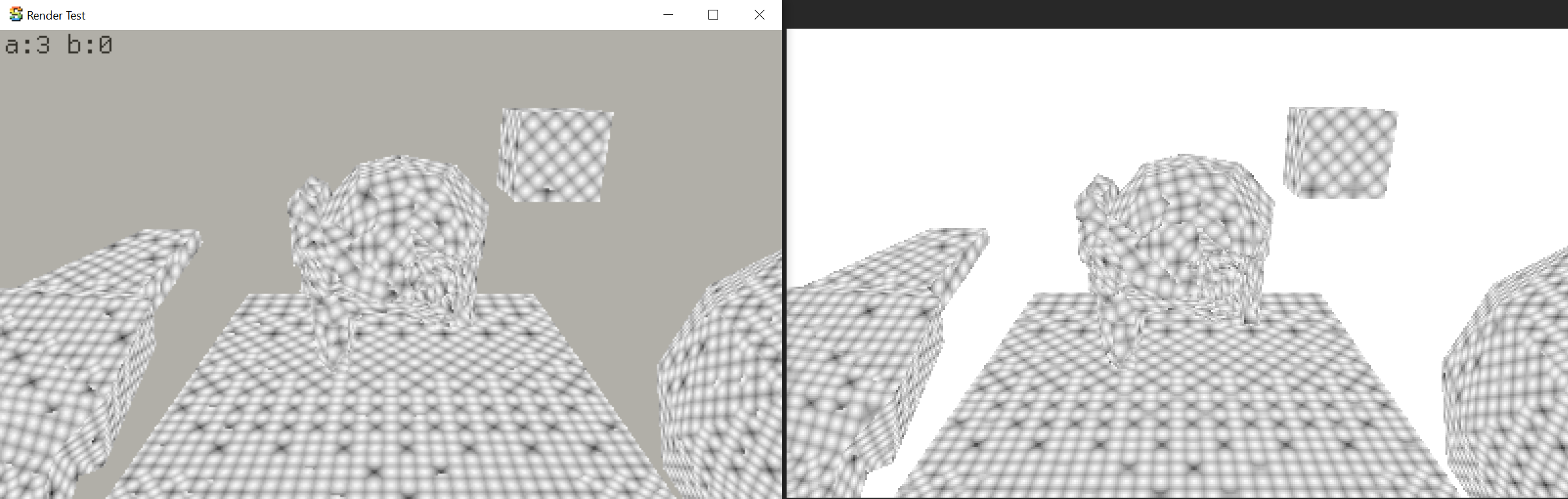
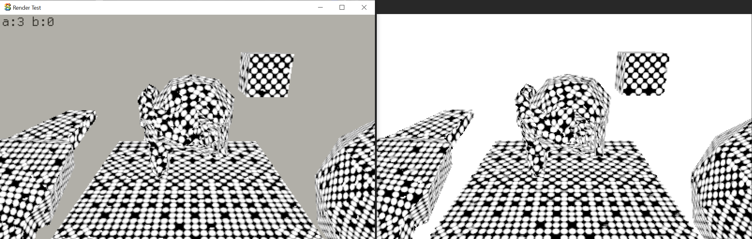
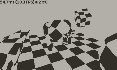
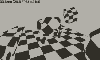
So let’s try it out. Here’s the same scene, with just a pure black/white checkerboard pattern based on mesh
UVs. My existing halfspace/barycentric rasterizer, and the one from Mini3D+ respectively:
Immediate notes:
- Yes the scanline rasterizer (for UV based checkerboard at least) is faster using the scanline approach (54ms halfspace, 33ms scanline),
- However the scanline one has more “artifacts”: stray black pixels near edge of plane/cube, and in general things are shifted by a pixel here and there for some reason. At this point I do not know which one is “more correct” however, but the difference was bothering me :)
- The checkerboard lines are “more wiggly” in the scanline one, most visible on the “floor” object.
I tried to “port” the dithering effect to this rasterizer, but got lost in trying to calculate the correct UV derivatives (horizontal ones are easy, vertical ones are harder). And the subtle rendering differences were bothering me, so I decided to actually read up about scanline rasterizers. The seminal series on them are from 1995/1996, by Chris Hecker for Game Developer Magazine. Hecker has the archive and the code drop at his website: Perspective Texture Mapping.
So! Taking the initial (fully floating point) rasterizer from Hecker’s code, the UV based checkerboard
renders like this:

This one runs slower than Mini3D+ one (42ms), but does not have stray “black pixels” artifacts around some mesh edges, and the lines on the floor are no longer wiggly. However, it is slightly different compared to the halfspace one! Why? This has nothing to do with task at hand, but the fact was bothering me, so…
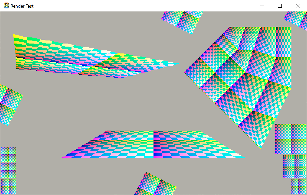
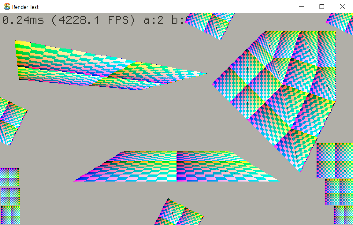
Comparing Scanline Rasterizers to actual GPU
Again using my “colored debug overlay on PC build” feature, I made a synthetic “test scene” with various cases of UV mapped geometry, with cases like:
- Checkerboard should map exactly 1:1 to pixels, at regular orientation, and geometry being rotated by exactly 90 degrees,
- The same, but geometry coordinates being shifted by less than half a pixel; the result should look the same.
- Some geometry that should be exactly one pixel away from screen edge,
- Some geometry where each checkerboard square should map to 1.5 (will have aliasing patterns) or 2 (should be exact) screen pixels.
- Several cases of perspective projection,
- Several cases of geometry being clipped by screen edges.
Here’s how it is rendered by the halfspace/barycentric rasterizer:

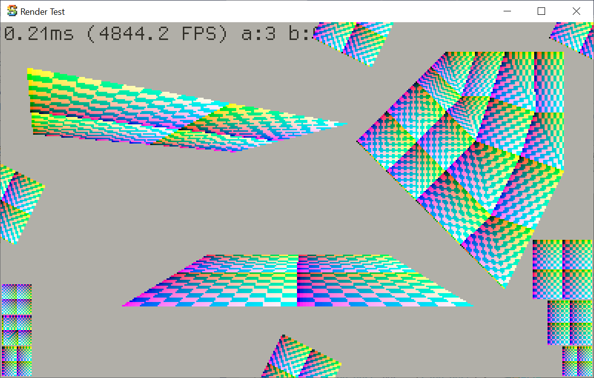
And then I made a simple Unity shader & C# script that renders exactly the same setup, using actual GPU. Here it is (pasted
into the same window frame as the test app):
Not exactly the same, but really close, I’ll claim this is acceptable (FWIW, GPUs use 8 bits subtexel precision, whereas my code uses 4 bits).
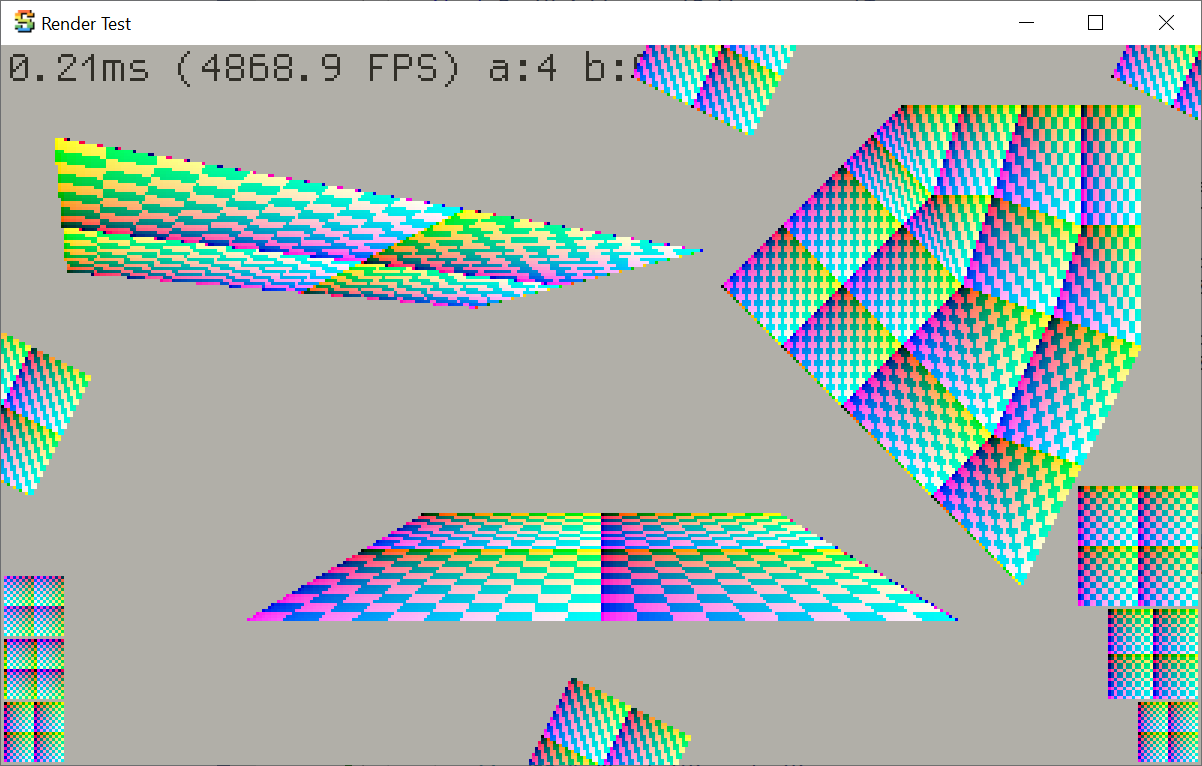
The rasterizer from Mini3D+ however looks much more different: 1) some cases do not map checkerboard to pixels 1:1,
2) the artifacts between some faces is where the rasterizer is not “watertight” and neighboring faces both
write to the same pixels, 3) some cases where geometry should be exactly one pixel away from screen edge are actually not.
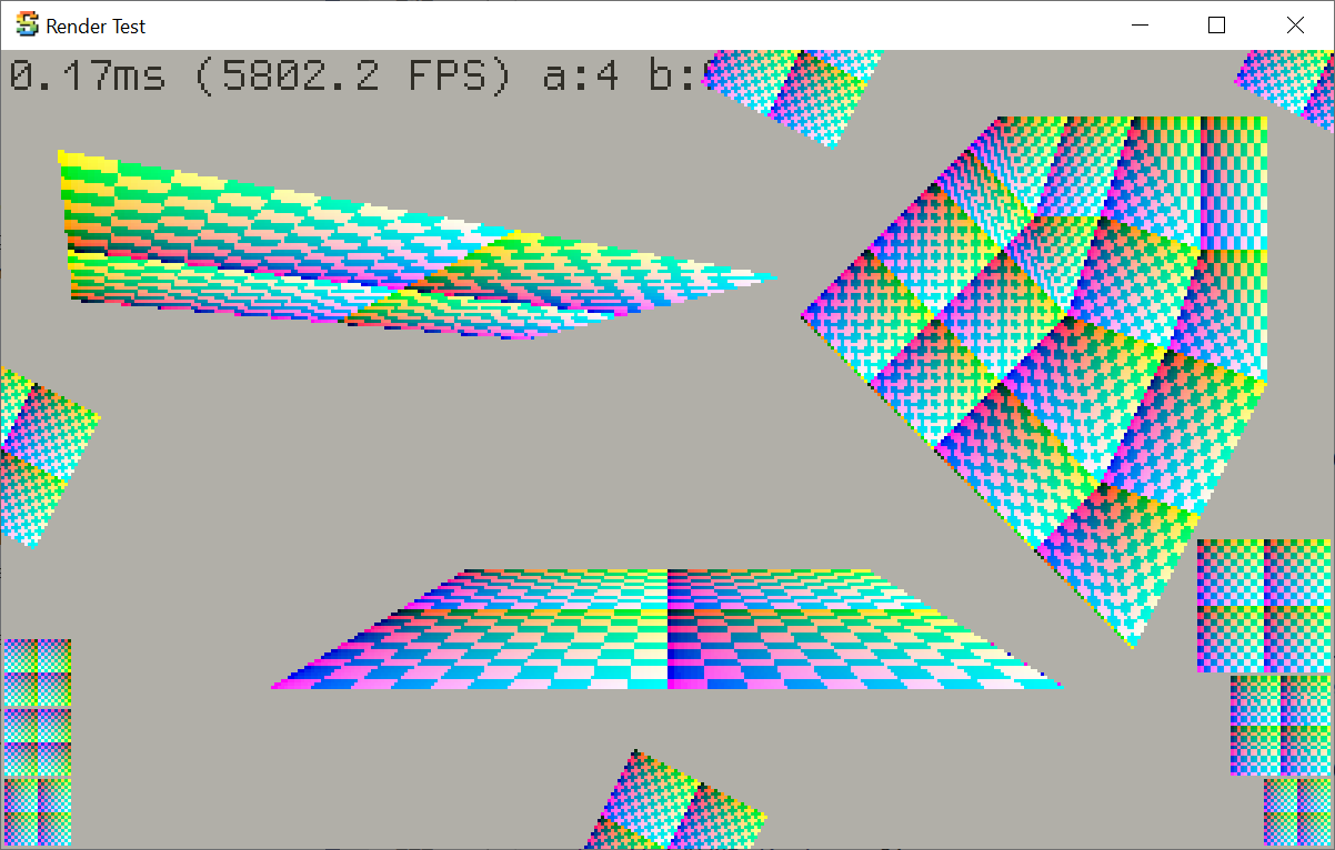
Hecker’s “fully floating point” rasterizer looks better, but still a lot more different from what the GPU does.
The fixed point, sub-dividing affine span rasterizer from Hecker’s code (i.e. the last iteration before the assembly-optimized
one) looks like this however. It fixes some artifacts from the previous one, but still covers slightly different pixels
compared to the GPU, and introduces UV wrapping artifacts at right sides of some planes.
My understanding of the difference is that maybe Hecker’s rasterizer follows pre-Direct3D 10 coordinate conventions, i.e. where pixel integer coordinates are placed directly on pixel centers. From part 3 of the article series, there’s this bit:
I chose the corresponding screen coordinates for the destination. I wanted the destination pixel centers to map exactly to the source pixel centers.
And when talking about how one would map a texture directly to screen at 1:1 ratio, he talks about adding -0.5 offset to the coordinates. This sounds very much like what people back in Direct3D 8/9 times had to always keep in mind, or try to solve that automatically in all their shaders.
While this coordinate system intuitively makes sense (pixel centers are at integer coordinates, yay!), eventually everyone realized it causes more problems down the line. The official DirectX Specs website minces no words:
D3D9 and prior had a terrible Pixel Coordinate System where the origin was the center of the top left pixel on the RenderTarget
Armed with that guess, I changed
the Hecker’s rasterizer code to shift positions by half a pixel, and remove the complexicated dUdXModifier dance
it was doing. And it became way closer to what the GPU is doing:
The fixed point, subdividing affine Hecker’s rasterizer with the above fix was more correct than the one from Mini3D+, and running a tiny bit faster by now. So I left only that code, and proceeded with it.
Back to scanline rasterizer
Initial “port” of the Fractal Dithering to the scanline rasterizer was at 102ms, i.e. slower than
halfspace one (63ms). But, I was calculating the UV derivatives for every pixel. Derivatives along
X axis are cheap (just difference to next pixel, which the inner scanline loop already does),
but the vertical ones I was doing in a “slow but correct” way.
The derivatives change fairly slowly across the triangle surface however, so what if I calculate
dU/dY and dV/dY only at the scanline endpoints, and just interpolate it across? This gets us
down to 71ms.
But hey! Maybe I do not need the per-pixel UV derivatives at all? The whole reason for derivatives
is to calculate the dither pattern spacing. But, at least in my scenes, the spacing varies very slowly
(if at all) across the triangle surface. Recall the previous visualization:
I can just calculate the derivatives at triangle vertices, do all the dither spacing calculations there, and interpolate spacing value across the triangle. 56ms!
Then, do the 3D lookup math directly from fixed point UVs that are interpolated
by the rasterizer. The previous “replace division by exp2” trick by working on floating
point bits is even simpler in fixed point: just shift by the provided integer
amount, and take the fractional bits as needed. 50ms

And the final optimization step I did so far has nothing to do with dithering step itself: the higher level code was transforming all mesh triangles, calculating their normals for lighting, then sorting them by distance, and finally rasterizing them back-to-front. Here the triangles that are back-facing, outside of the screen, or zero-area are culled. I moved the triangle culling to happen before sorting (there’s no point in sorting invisible triangles anyway), and now the scanline dither effect runs at 45ms (halfspace one at 60ms).
That’s it for now!
So, this scene runs at 45ms (20-22FPS) on the Playdate device right now, which is much better than the initial 830ms (1.2FPS). Can it be made yet faster? Most likely.
Does it make it a practical effect on the Playdate? Dunno, it is quite heavy and at this low resolution, does not look very good (it does not help that some approximations/simplifications I did actually increase dither pattern aliasing).
But hey, this was fun! I learned a thing or three. And if you want either a scanline or a halfspace rasterizer for Playdate that very closely matches what actual GPU would do (i.e. it is a more correct rasterizer than mini3d from Playdate SDK or Mini3D+), you can find them at github.com/aras-p/playdate-dither3d