A way to visualize mip levels
Recently a discussion on Twitter about folks using 2048 textures on a pair of dice spawned this post. How do artists know if the textures are too high or too low resolution? Here’s what we do in Unity, which may or may not work elsewhere.
When you have a game scene that, for example, looks like this:
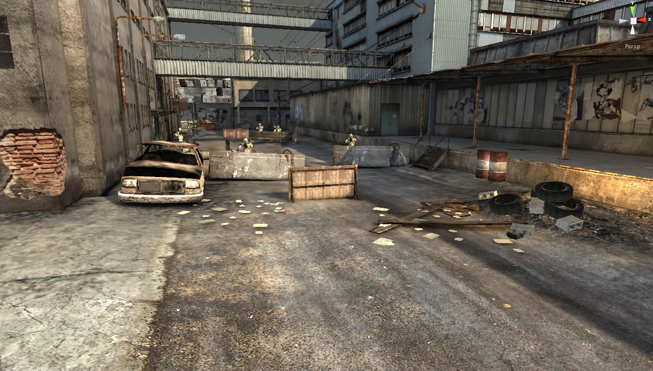
We provide a “mipmaps” visualization mode that renders it like this:
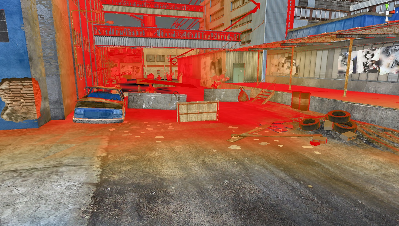
Original texture colors mean it’s a perfect match (1:1 texels to pixels ratio); more red = too much texture detail; more blue = too little texture detail.
That’s it, end of story, move along!
Now of course it’s not that simple. You can just go and resize all textures that were used on the red stuff. The player might walk over to those red objects, and then they would need more detail!
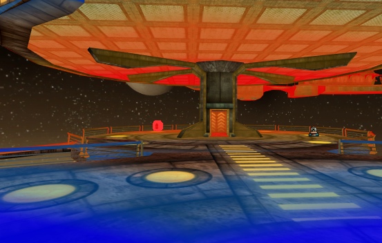
Also, the amount of texture detail needed very much depends on the screen resolution the game will be running at:

Still, even with varying resolution sizes and the fact that the same objects in 3D can be near & far from the viewer, this view can answer the question of “does something have a too high/too low texture detail?”, mostly by looking at colorization mismatch between nearby objects.
In the picture above, the railings have too little texture detail (blue), while the lamp posts have too much (red). The little extruded things on the floating pads have too much detail as well.
The image below reveals that floor and ceiling have mismatching texture densities: floor has too little, while ceiling has too much. Probably should be the other way around, in a platform you’d more often be looking at the floor.
How to do this?
In the mipmap view shader, we display the original texture mixed with a special “colored mip levels” texture. The regular texture is sampled with original UVs, while the color coded texture is sampled with more dense ones, to allow visualization of “too little texture detail”. In shader code (HLSL, shader model 2.0 compatible):
struct v2f {
    float4 pos : SV_POSITION;
    float2 uv : TEXCOORD0;
    float2 mipuv : TEXCOORD1;
};
float2 mainTextureSize;
v2f vert (float4 vertex : POSITION, float2 uv : TEXCOORD0)
{
    v2f o;
    o.pos = mul (matrix_mvp, vertex);
    o.uv = uv;
    o.mipuv = uv * mainTextureSize / 8.0;
    return o;
}
half4 frag (v2f i) : COLOR0
{
    half4 col = tex2D (mainTexture, i.uv);
    half4 mip = tex2D (mipColorsTexture, i.mipuv);
    half4 res;
    res.rgb = lerp (col.rgb, mip.rgb, mip.a);
    res.a = col.a;
    return res;
}
The mainTextureSize above is the pixel size of the main texture, for example (256,256). Division by eight might seem a bit weird, but it really isn’t!
To show the colored mip levels, we need to create mipColorsTexture that has different colors in each mip level.
Let’s say we would create a 32x32 size texture for this, and the largest mip level would be used to display “ideal texel to pixel density”. If the original texture was 256 pixels in size and we want to sample a 32 pixels texture at exactly the same texel density as the original one, we have to use more dense UVs: newUV = uv * 256 / 32 or in a more generic way, newUV = uv * textureSize / mipTextureSize.
Why there’s 8.0 in the shader then, if we create the mip texture at 32x32 size? That’s because we don’t want the largest mip level to indicate “ideal texel to pixel” density. We also want a way to visualize “not enough texel density”. So we push the ideal mip level two levels down, which means it’s four times UV difference. That’s how 32 becomes 8 in the shader.
The actual colors we use for this 32x32 mipmaps visualization texture are, in RGBA: (0.0,0.0,1.0,0.8); (0.0,0.5,1.0,0.4); (1.0,1.0,1.0,0.0); (1.0,0.7,0.0,0.2); (1.0,0.3,0.0,0.6); (1.0,0.0,0.0,0.8). Alpha channel controls how much to interpolate between the original color and the tinted color. Our 3rd mip level has zero alpha so it displays unmodified color.
Now, step 2 is somehow forcing artists to actually use this ;)